Introduction #
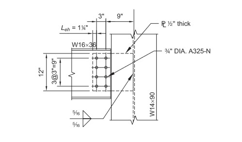
In previous article, we talked about how to design a single plate, beam to column flange connection. This article will discuss how to design a extended configuration single plate by CET.Calculators. We are using the example form AISC 14th Design Example IIA-19. Again, since we will use Typora to create PDF report, user could download Typora and add following lines to resources/window.html in Typora directory, to align equation to the left and show nice equations/outputs.
window.MathJax = {
  ....
  svg: {
    displayAlign: 'left',
    scale: 0.9,
    minScale: 80,
  },
...
};
The Extended Configuration of Single Plate #
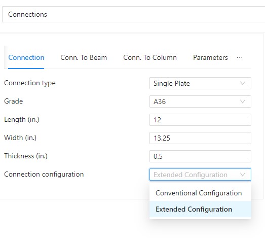
After reading the contents of Chapter 10 AISC 14th Manal, users will find that the single plate connections with extended configuration have less constraints then the conventional configuration. Theoretically, a single plate can be designed for both configurations. Therefore, different form other software, the Connection Calculator has a drop list for configuration (shown in picture below) and let user make the decision. According to page 10-104 of AISC 14th Manual, for extended configuration, the Connection Calculator checks Item 2 to 5 in the Design Checks, such as:

- Maximum plate thickness
- Limit state of shear yielding, shear rupture and block shear
- Limit state of shear yielding, shear buckling and yielding due to flexure
- Limit state of plate buckling
For AISC 14th Design Example IIA-19, the input data is following block. User can copy and paste them to the left/top panel of the Connection Calculator, “Parameters” tab.
{
  "beam": {
    "bolts": {
      "edge_dist_para": "1.25",
      "edge_dist_prep": "1.5"
    },
    "gap": 0.5,
    "grade": "A992",
    "size": "W16X36"
  },
  "column": {
    "grade": "A992",
    "size": "W14X90"
  },
  "conn": {
    "bolts": {
      "column": "2",
      "column_spacing": "3",
      "diameter": "0.75",
      "ecc_dist_para": "10.5",
      "edge_dist_para": "1.5",
      "edge_dist_prep": "1.25",
      "gage": "3.5",
      "grade": "A325N",
      "hole_type": "Standard",
      "row": "4",
      "row_spacing": "3",
      "to_conn_face_para": "3",
      "to_conn_face_perp": "9"
    },
    "length": "12",
    "grade": "A36",
    "thickness": "0.5",
    "type": "Single Plate",
    "width": "13.25",
    "welds": {
      "FEXX": 70,
      "size": 0.3125,
      "type": "Double Fillet"
    },
    "config": "Extended Configuration"
  },
  "part": {
    "axial_force": "`",
    "code": "AISC 14th",
    "measure_unit": "Imperial Units",
    "method": "ASD",
    "memberFraming": "Beam To Column Flange",
    "moment": "0",
    "check_force": "24",
    "version": 0.04
  }
}
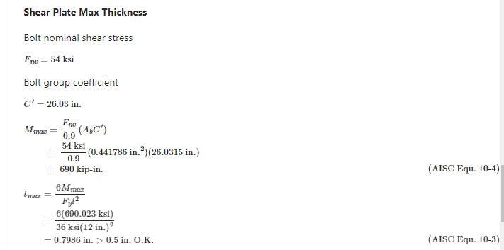
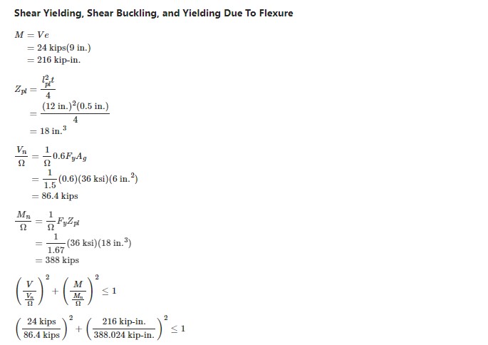
The calculations will show in the right panel. For example, the check of maximum plate thickness and the check of shear yielding, shear buckling and yielding due to flexure. Besides, users still need to read AISC Manual Chapter 10, to understand the difference between conversional configuration and extended configuration for single plate connections, such as the bolt group eccentricity and many others.


Compare Results with AISC 14th Design Example IIA-19 #
| Check part | Check item | CET.Calculator | AISC 14th Example IIA-19 | Difference |
| Beam web | Shear yield | 93.8 kips | N/A | |
| Hole bearing | 40 kips | N/A | ||
| Single plate (in beam web) | Bolt shear | 27.65 kips | 27.7 kips | 0 |
| Shear yield | 86.4 kips | 86.4 kips | 0 | |
| Shear rupture | 73.95 kips | 74 kips | 0 | |
| Hole bearing | 56.4 kips | N/A | ||
| Block shear | 78 kips | 77.8 kips | 0 | |
| Weld | 105.6 kips | N/A | 0 | |
| Max thickness | 0.7986 in. | 0.799 in. | 0 | |
| Shear yielding, shear buckling and yielding due to Flexure | 0.387 | 0.387 | 0 | |
| Plate buckling | 258.7 kip-in. | N/A | ||
| Flexural rupture | 369.8 kip-in. | 371 kip-in. | 0.2 % |
Conclusion #
- The Connection Calculator of CET.Calculators can design a single plate in extended configuration.
- Users could choose to design a single plate connection in conversional or extended configuration.
- The calculations in Connection Calculator are accurate, compare to AISC 14th Design Example IIA-19.


