Before start #
FreeCAD is a great, open-source CAD software. It has a BIM workbench, but it is not designed for steel member design or steel connection design like other software. CET.SteelConnDesign extends the functionalities of FreeCAD and it is working with FreeCAD seamlessly.
Run CET.SteelConnDesign #
Users can get CET.SteelConnDesign for free right now. After download the zip file, please extract to any folder. Now there are two new folders: “FreeCAD0.20” and “CET.SteelConnDesign”.
1) Go to “FreeCAD0.20/bin” and run FreeCAD.exe (you can create a shortcut for this exe file);
2) Open “Execute macro” dialog (in Menu “Macro”, “Macros …”) and change the “User macros location” to the place where “CET.SteelConnDesign” folder is;
3) Execute “CET_SCD.py”
4) Please wait until the CET.SteelConnDesign module is loaded into FreeCAD (may take a minute dispends on machine speed).
Start with CET.SteelConnDesign #
There are 4 ways to start with CET.SteelConnDesign:
1) Start from examples
2) Load project file
3) Scan existing FreeCAD model
4) Create members by entering data
Work with CET.SteelConnDesign examples #
The easiest way to start with CET.SteelConnDesign is using examples. In “Projects” tab, users can choose “Beam To Column Flange, Single Plate” from the example list. Then the FreeCAD model is show on the left window. Go to “Connection Design” tab and hit the “Design Connation” button, a set of connection solids will show in the right window. Now the user can change the input fields, undo or redo input data. The “Fit Solids” button will help user to review the connection solids and the “Show Report” button will display the HTML report.
Open/save CET.SteelConnDesign project file #
Users can open or save project files. These files will contain member and connection information. They are in binary format. Only premium users can use the plain json project files.
Scan existing FreeCAD model #
If you have a FreeCAD file, users can open it first then run “CET_SCD.py”. The sequence is important. In “Projects” tab, when “Scan Model” button is clicked, all member information will be brought to CET.SteelConnDesign. However, since FreeCAD does not design or store connection information, scanning model only works about members.
Create members by entering data #
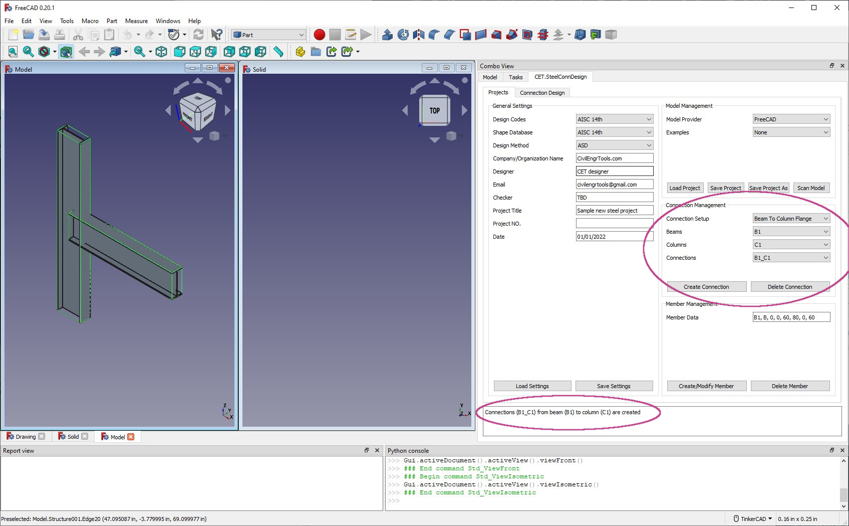
In CET.SteelConnDesign, users can fully control FreeCAD model data. For a empty project, in “Projects” tab “Member Data” input field, users can create a column by entering “C1, C, 0, 0, 0, 0, 0, 120“, which creates a member with name “C1”, type as column (“C” – column, “B” – beam, “BR” – brace (not support yet)), “0, 0, 0” as start point and “0, 0, 120” as the end point. When the “Create/Modify Member” button is clicked, a column will be created. Based on the similar procedure, “B1, B, 0, 0, 60, 80, 0, 60” will create a beam with name “B1”, start from “0 0 60” and end at “80 0 60”. All units are in inch. Note that the member grade and size are specified yet. Users can change them in the connection design.
Design Steel Connections #
Create connections #
Once beams and columns are loaded or created, users need to create connections before the connection design. In “Projects” tab, if the connection is not shown in “Connections” list, users can select beam and column from “Beams” and “Columns” list, choose the correct setup type and create a connection. Once the new connection is created, it will show in the connection list. Please note, the “Connection Setup” type is very important. Letting a beam connecting to column flange or web will lead to total different design. In fact, we have finished the research work about automatically finding connection setups. We will add this function in scanning FreeCAD/Tekla models soon.

Switch between Connection Parts #
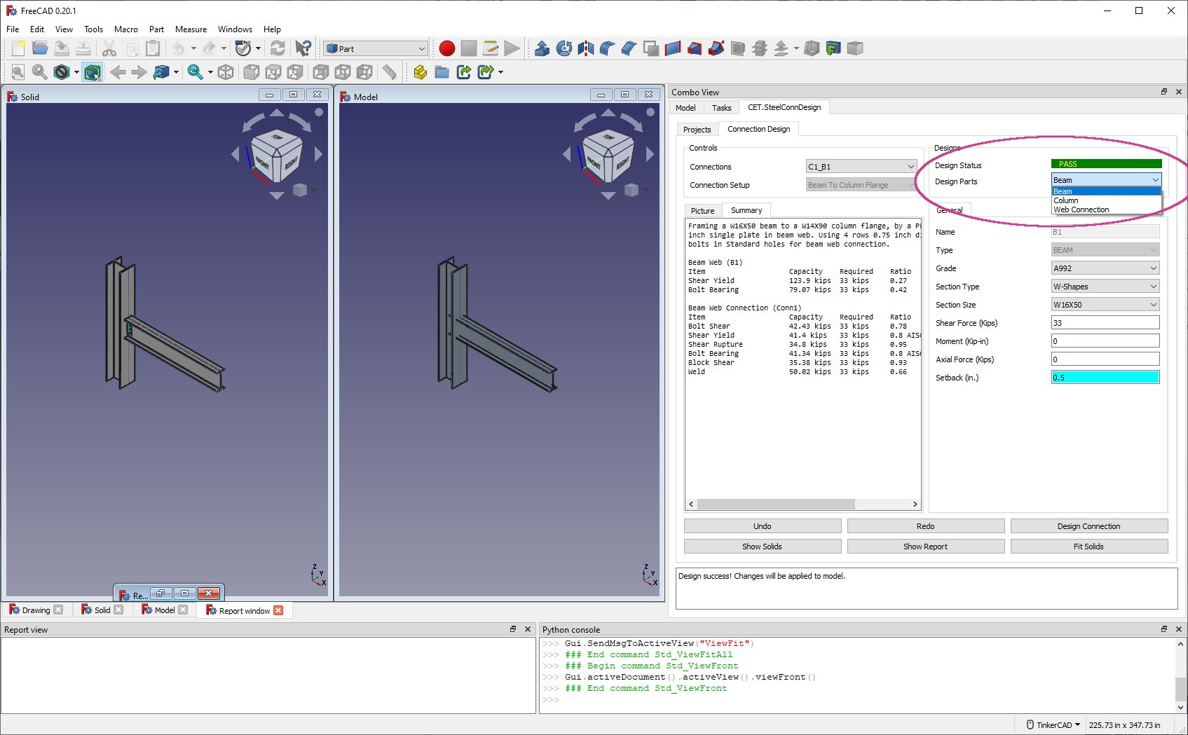
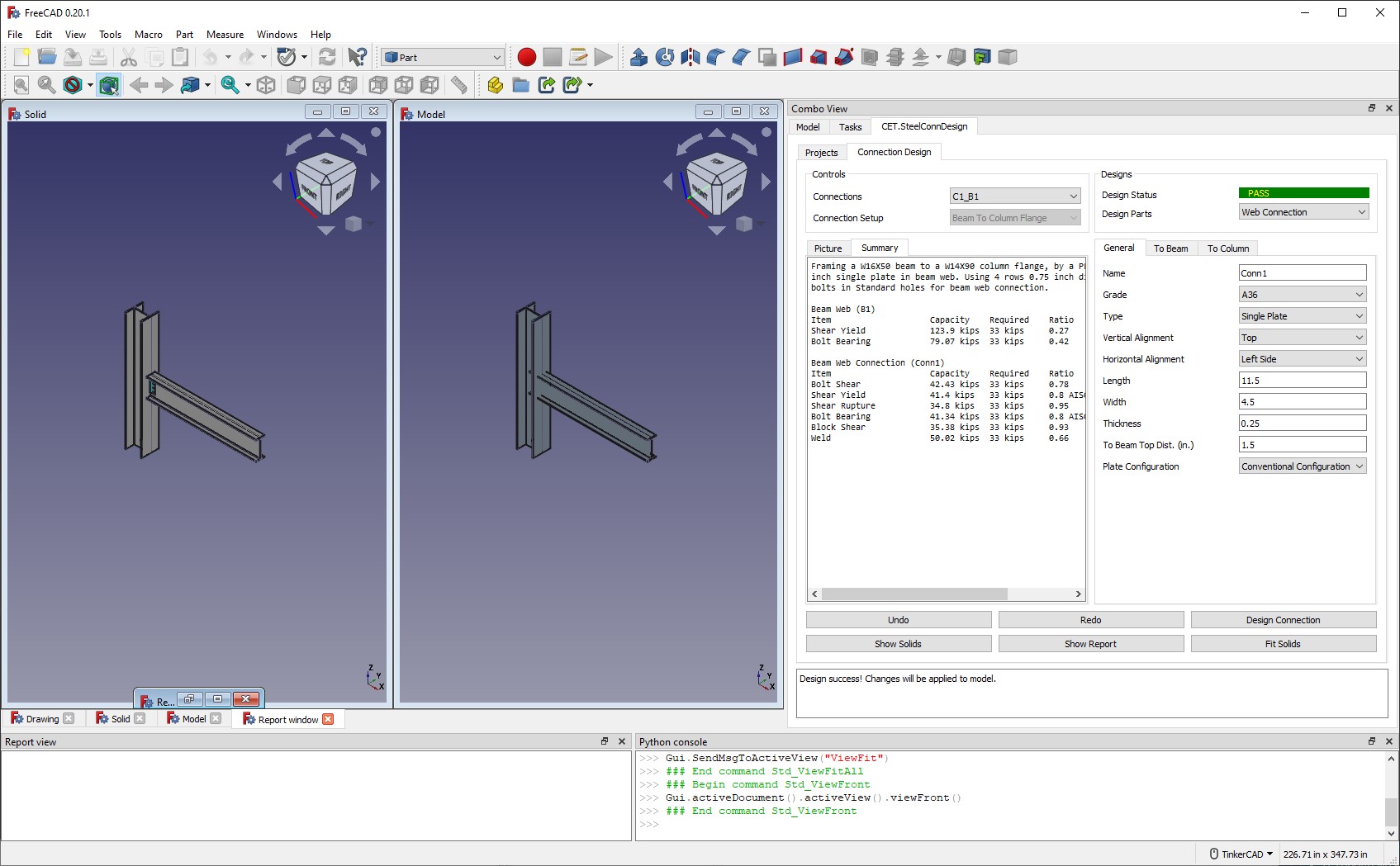
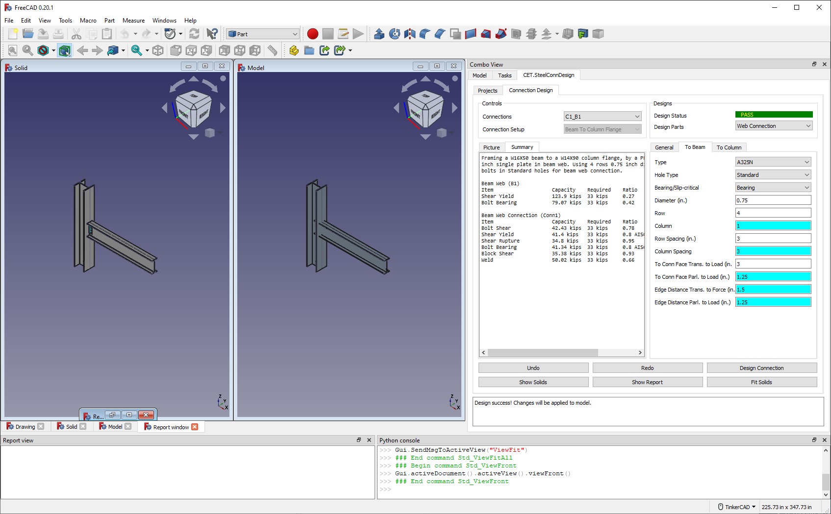
Once the connection is created, users can switch between each design parts. The design philosophy of CET.SteelConnDesign is that only one connection/member/part is shown and designed at UI each time. For the current example, users can choose to design beam/column/web connection. When choosing “Beam” as the design part, users can enter shear load and change beam grade/size. Note that for “Web Connection” part, there are 3 tabs. The “General” tab is about connection information and “To Beam” tab has all bolt input fields


