Create 2D drawings #
CET.Calculators is far beyond a traditional calculator. It can create 2D drawings. For example, users can copy following lines to the Connection Calculator, left panel, “Parameters” tab:
{
  "beam": {
    "bolts": {
      "edge_dist_para": "1.25",
      "edge_dist_prep": "1.5"
    },
    "gap": 0.5,
    "grade": "A992",
    "size": "W16X50"
  },
  "column": {
    "grade": "A992",
    "size": "W14X90"
  },
  "conn": {
    "bolts": {
      "column": "1",
      "column_spacing": "3",
      "diameter": "0.75",
      "ecc_dist_para": "1.5",
      "edge_dist_para": "1.25",
      "edge_dist_prep": "1.5",
      "gage": "3.5",
      "grade": "A325N",
      "hole_type": "Standard",
      "row": "4",
      "row_spacing": "3",
      "to_conn_face_para": "1.25",
      "to_conn_face_perp": "3",
      "pattern": "4 Bolts"
    },
    "length": "11.5",
    "grade": "A36",
    "thickness": "0.25",
    "type": "Single Plate",
    "width": "4.5",
    "welds": {
      "FEXX": 70,
      "size": 0.1875,
      "type": "Double Fillet"
    },
    "side": "Left Side",
    "dist_to_member_top": "1.5"
  },
  "part": {
    "axial_force": "0",
    "code": "AISC 14th",
    "measure_unit": "Imperial Units",
    "method": "ASD",
    "moment": "0",
    "check_force": "33",
    "version": 0.05,
    "config": "Conventional Configuration",
    "memberFraming": "Beam To Column Flange"
  }
}
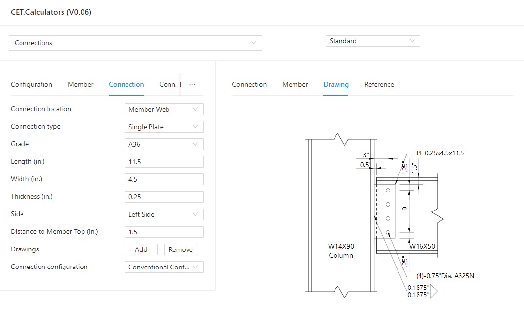
and then in “Connection” tab, click “Add” button. In the right panel, choosing “Drawing” tab, the 2D drawing will show as following picture. This is the example from AISC 14th Design Example IIA-17.

Users can change the inputs in the left panel and the 2D drawing will show the changes instantly.
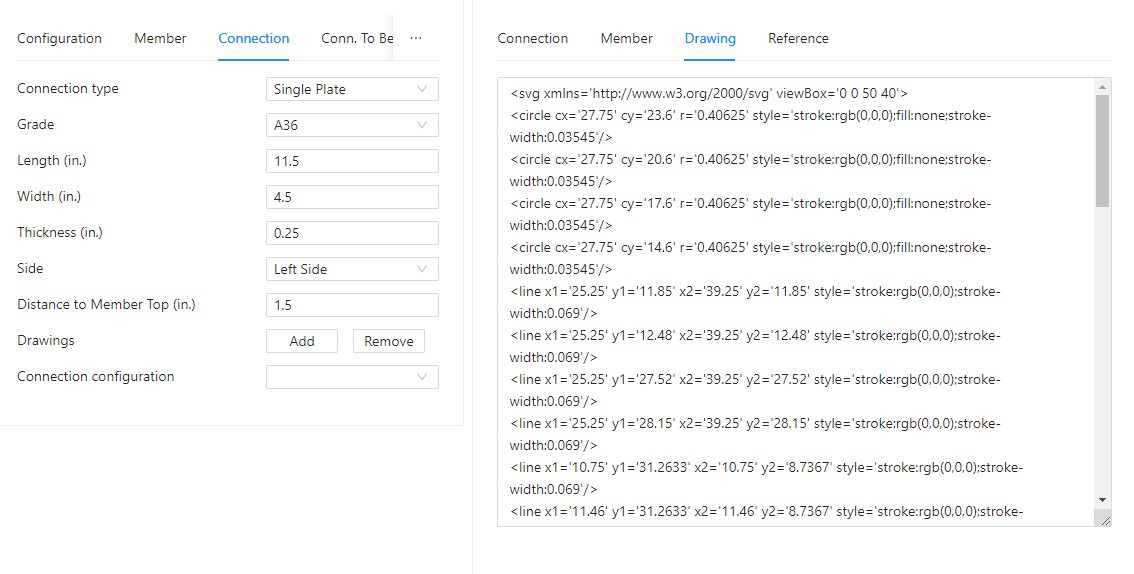
When users changing the display from “Standard” to “Markdown“, the 2D drawing in SVG format appears. Users copy and paste the SVG contents and save as a “drawing.svg” file by any text editor.

The in same directory of “drawing.svg” file, create a “example.md” file with following line:
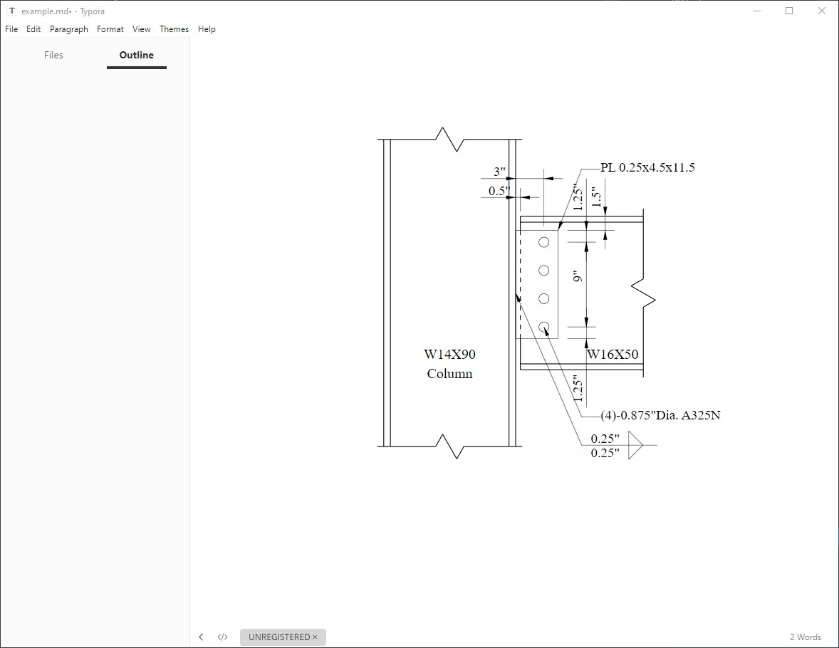
When users open “example.md” by Typora, the drawings will show. VSCode also can display the drawings in its Preview mode. Of course, users can edit drawing.svg by Inkscape and others, to add notes, callouts and many others.

Limitations #
- Only for beam to column single plate, non-moment connections.
- Do not support notes, dimensions, callouts (they are coming soon).
- Only support SVG format. DXF format will be available soon.


